21st Century Learning and Teaching
586.7K views | +11 today
Follow
21st Century Learning and Teaching
Related articles to 21st Century Learning and Teaching as also tools...
Curated by Gust MEES
Your new post is loading...

Popular Tags

Current selected tags: 'Creativity', 'OLED'. Clear
Scooped by Gust MEES
Scoop.it!

Arduino OLED Display Graphics Tutorial | #Coding #Maker #MakerED #MakerSpaces

Arduino OLED Display Graphics Tutorial | #Coding #Maker #MakerED #MakerSpaces | 21st Century Learning and Teaching | Scoop.it

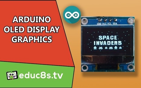
Dear friends welcome back. Today we’re going to see how to display are custom-made bitmap graphics on this tiny OLED display using Arduino. It is my first OLED Display Graphics tutorial. Let’s start! Intro to the Arduino OLED Display Graphics Tutorial In this Arduino OLED Display Graphics Tutorial, we are using the tiny and very …


Learn more / En savoir plus / Mehr erfahren:


https://www.scoop.it/t/21st-century-learning-and-teaching/?&tag=ARDUINO


https://www.scoop.it/t/21st-century-learning-and-teaching/?&tag=OLED


Gust MEES's insight:

Dear friends welcome back. Today we’re going to see how to display are custom-made bitmap graphics on this tiny OLED display using Arduino. It is my first OLED Display Graphics tutorial. Let’s start! Intro to the Arduino OLED Display Graphics Tutorial In this Arduino OLED Display Graphics Tutorial, we are using the tiny and very …


Learn more / En savoir plus / Mehr erfahren:


https://www.scoop.it/t/21st-century-learning-and-teaching/?&tag=ARDUINO


https://www.scoop.it/t/21st-century-learning-and-teaching/?&tag=OLED


No comment yet.
Scooped by Gust MEES
Scoop.it!

0.96 Inch OLED I2C Display 128 x 64 | Arduino Tutorial | #Coding #Maker #MakerED #MakerSpaces #LEARNingByDoing 

0.96 Inch OLED I2C Display 128 x 64 | Arduino Tutorial | #Coding #Maker #MakerED #MakerSpaces #LEARNingByDoing  | 21st Century Learning and Teaching | Scoop.it

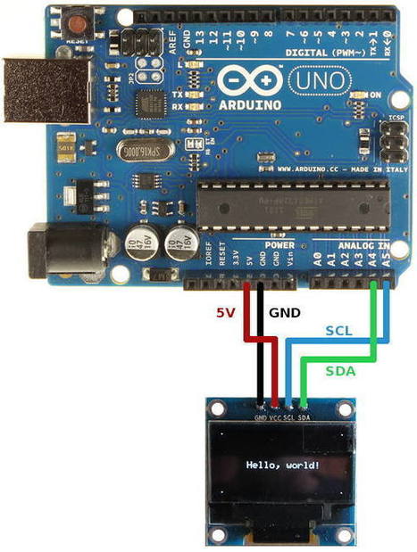
How to connect and program the Geekcreit 0.96 inch 4 pin white I2C OLED module with Arduino. OLED display based on a SSD1306 OLED driver IC.

In this tutorial a 0.96 inch monochrome OLED display from Geekcreit is connected or interfaced to an Arduino. Libraries are then installed and some example programs run which show how to use the display in an Arduino sketch.

The display connects to Arduino using only four wires – two for power and two for data, making the wiring very simple. The data connection is I2C (I²C, IIC or Inter-Integrated Circuit). This interface is sometimes called TWI (Two Wire Interface).

At the very lowest level, the Arduino Wire library is used to communicate with the display. Libraries are available that make it easy to start using the display right away to display text and graphics. These libraries are installed in this tutorial.


[Gust MEES] It works with THIS OLED <===> https://www.amazon.de/dp/B01L9GC470


Learn more / En savoir plus / Mehr erfahren:


https://www.scoop.it/t/21st-century-learning-and-teaching/?&tag=ARDUINO


Gust MEES's insight:

How to connect and program the Geekcreit 0.96 inch 4 pin white I2C OLED module with Arduino. OLED display based on a SSD1306 OLED driver IC.

In this tutorial a 0.96 inch monochrome OLED display from Geekcreit is connected or interfaced to an Arduino. Libraries are then installed and some example programs run which show how to use the display in an Arduino sketch.

The display connects to Arduino using only four wires – two for power and two for data, making the wiring very simple. The data connection is I2C (I²C, IIC or Inter-Integrated Circuit). This interface is sometimes called TWI (Two Wire Interface).

At the very lowest level, the Arduino Wire library is used to communicate with the display. Libraries are available that make it easy to start using the display right away to display text and graphics. These libraries are installed in this tutorial.


[Gust MEES] It works with THIS OLED <===> https://www.amazon.de/dp/B01L9GC470


Learn more / En savoir plus / Mehr erfahren:


https://www.scoop.it/t/21st-century-learning-and-teaching/?&tag=ARDUINO


No comment yet.
Scooped by Gust MEES
Scoop.it!

Bitmaps & Code | OLED SlideShow | Steampunk Cameo Necklace with OLED Display | Adafruit Learning System | #Coding #Maker #MakerED #MakerSpaces

Bitmaps & Code | OLED SlideShow | Steampunk Cameo Necklace with OLED Display | Adafruit Learning System | #Coding #Maker #MakerED #MakerSpaces | 21st Century Learning and Teaching | Scoop.it

Bitmaps & Code by Leslie Birch


Time to create two image files and convert them into a code the OLED can understand.

Use Photoshop or another imaging program to create two cameo profile pics and turn them into bitmaps (.bmp). They should be monologue and 128x64 pixels. Notice I had my images each facing another direction.


Download LCD Image Converter and run.


Choose New Image and create a name. Then hit enter.
Now choose Image and Import. Select the file.
Now choose Options and Conversion, then Prepare. The followiing should be checked: Type:  Monochrome, Threshold Dither, Main Scan Direction: Left to Right, Line Scan Direction: Forward 
Now select Image. Make sure Select to Rows is checked. 8-Bit and Little Endian.


Hit OK, then File, Convert. Name the file. Now do the same process for your other file. The completed files will contain a series of code that you need to cut and paste into the project code to replace the files I provided. It will look something like this, only longer. Note that you don't need the beginning name, just the brackets and what is contained within them...


Learn more / En savoir plus / Mehr erfahren:


https://www.scoop.it/t/21st-century-learning-and-teaching/?&tag=ARDUINO


https://www.scoop.it/t/21st-century-learning-and-teaching/?&tag=OLED


Gust MEES's insight:

Bitmaps & Code by Leslie Birch


Time to create two image files and convert them into a code the OLED can understand.

Use Photoshop or another imaging program to create two cameo profile pics and turn them into bitmaps (.bmp). They should be monologue and 128x64 pixels. Notice I had my images each facing another direction.


Download LCD Image Converter and run.


Choose New Image and create a name. Then hit enter.
Now choose Image and Import. Select the file.
Now choose Options and Conversion, then Prepare. The followiing should be checked: Type:  Monochrome, Threshold Dither, Main Scan Direction: Left to Right, Line Scan Direction: Forward 
Now select Image. Make sure Select to Rows is checked. 8-Bit and Little Endian.


Hit OK, then File, Convert. Name the file. Now do the same process for your other file. The completed files will contain a series of code that you need to cut and paste into the project code to replace the files I provided. It will look something like this, only longer. Note that you don't need the beginning name, just the brackets and what is contained within them...


Learn more / En savoir plus / Mehr erfahren:


https://www.scoop.it/t/21st-century-learning-and-teaching/?&tag=ARDUINO


https://www.scoop.it/t/21st-century-learning-and-teaching/?&tag=OLED


No comment yet.
Scooped by Gust MEES
Scoop.it!

10 oled Projects - Arduino Project Hub | #Coding #Maker #MakerED #MakerSpaces #LEARNingByDoing

10 oled Projects - Arduino Project Hub | #Coding #Maker #MakerED #MakerSpaces #LEARNingByDoing | 21st Century Learning and Teaching | Scoop.it

Interested in oled? Explore 10 projects tagged with 'oled'. Find these and other hardware projects on Arduino Project Hub.


Learn more / En savoir plus / Mehr erfahren:


https://www.scoop.it/t/21st-century-learning-and-teaching/?&tag=ARDUINO


Gust MEES's insight:

Interested in oled? Explore 10 projects tagged with 'oled'. Find these and other hardware projects on Arduino Project Hub.


Learn more / En savoir plus / Mehr erfahren:


https://www.scoop.it/t/21st-century-learning-and-teaching/?&tag=ARDUINO


Jèét Sãlvî's curator insight, May 3, 2018 1:38 AM
Share your insight